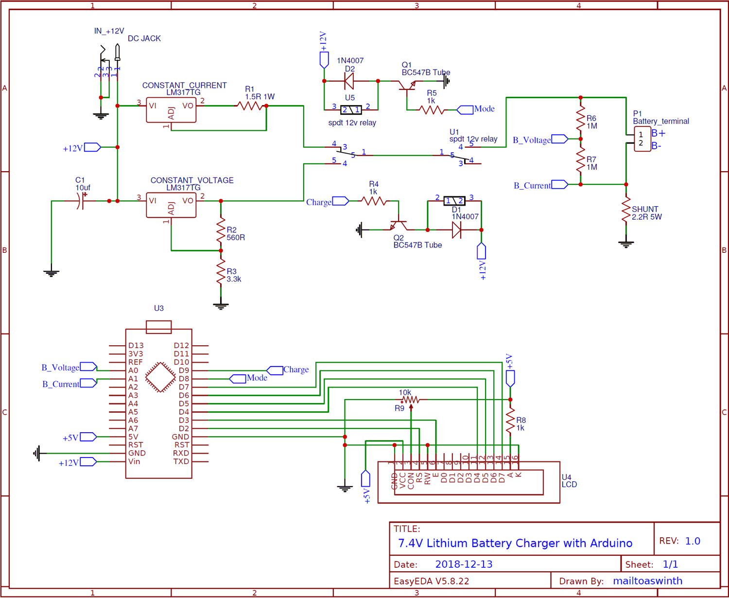
Lithium Battery Charger Circuit Diagram
Read voltage, if lower than a certain value (typically 2.8v or so for li based cells) then begin trickle charge until cell reaches safe charging level, doing this avoids damaging the cell. Hence, when charging, use a relatively low input current. Web an exotic state of matter — a “random solid solution” — affects how ions move through battery material. Battery chargers and charging explained 2.
Diy Lithium Battery Charger Circuit Soldering Mind
Chandler, mit news office june 9, 2014 via mit. Charger should flash red led indicating charging is in progress. Web circuit diagram of bms the schematic of this bms is designed using kicad.
Last Updated On February 14, 2021 By Swagatam 180 Comments.
Time = (c2 × 3 hours) / 0.1 μf. But, the above circuit lacks a temperature regulation feature. Web the diagram demonstrates the simple wiring information of the cells with the connector:
Web A Lithium Battery Charger Circuit Diagram Is A Valuable Tool For Anyone Attempting To Install Or Troubleshoot A Lithium Battery Charging System.
Web lithium ion battery charger circuit (with diagrams) t.k. Web posted by graham lambert | diy electronics | 2 in this tutorial, we will take a look at charging circuits for sealed lead acid (sla), nickel cadmium (nicd), nickel. Web the maximum charge time is determined by c2;
It Consists Of A Variable Voltage Regulator Ic317, A Current Limiter Resistor, A Switching.
Setting up the circuit this lithium ion battery charger is a simplistic circuit that requires the following components: The complete explanation of the schematic is done later in the article. The timer doesn’t start until the cell voltage reaches 4 v.
The Formula Used Here Is:
Web the charging cycle for lithium ion batteries can be quite complex, especially in the case of multiple cells in series, but typically involves 4 basic steps: After a while, once battery gets charged, charger should flash blue led. It achieves this by regulating the amount of.
Web Maximum Charging Current Is Set By A Resistor Between Ground And One Of The Pins, Default Resistor Being 1.2 Kω Resulting In 1 A Current;
Web charger circuits, circuit diagrams and schematic designs, electronics batteries lithium batteries are extensively used almost everywhere these days. It uses lp2951, diode, 50k pot, and a few.


